Mini proiect (24) - Programarea ESP32 CAM folosind Arduino uno - Configurarea a doua taskuri folosind biblioteca FreeRTOS
Programarea ESP32 CAM folosind Arduino uno - Configurarea a doua taskuri folosind biblioteca FreeRTOS
În acest articol descriu în detaliu configurarea și programare plăcii ESP32 CAM folosind Arduino UNO. În sketch-ul de test am folosit libraria FreeRTOS pentru a defini 2 taskuri de test în care activez intermitent blițul camerei foto.
ESP32 CAM este un modul de camera de dimensiuni reduse, cu consum redus de energie, bazat pe ESP32.Este dotat cu o camera OV2640 si ofera slot pentru carduri TF la bord.
ESP32 CAM poate fi utilizat pe scara larga in aplicatii IoT inteligente, cum ar fi monitorizarea video wireless, incarcarea de imagini WiFi, identificarea QR, etc.
Specificatii ESP32 CAM
- WIFI module: ESP-32S
- Processor: ESP32-D0WD
- Built-in Flash: 32Mbit
- RAM: Internal 512KB + External 4M PSRAM
- Antenna: Onboard PCB antenna
- WiFi protocol: IEEE 802.11 b/g/n/e/i
- Bluetooth: Bluetooth 4.2 BR/EDR and BLE
- WIFI mode: Station / SoftAP / SoftAP+Station
- Security: WPA/WPA2/WPA2-Enterprise/WPS
- Output image format: JPEG (OV2640 support only), BMP, GRAYSCALE
- Supported TF card: up to 4G
- Peripheral interface: UART/SPI/I2C/PWM
- IO port: 9
- UART baudrate rate: default 115200bps
- Power supply: 5V
- Transmitting power:
- 802.11b: 17 ±2dBm(@11Mbps)
- 802.11g: 14 ±2dBm(@54Mbps)
- 802.11n: 13 ±2dBm(@HT20,MCS7)
- Receiving sensitivity:
- CCK,1Mbps: -90 dBm
- CCK,11Mbps: -85 dBm
- 6Mbps(1/2 BPSK): -88 dBm
- 54Mbps(3/4 64-QAM): -70 dBm
- HT20,MCS7(65Mbps, 72.2Mbps): -67 dBm
- Power consumption:
- Flash off: 180mA@5V
- Flash on and brightness max: 310mA@5V
- Deep-Sleep: as low as 6mA@5V
- Modern-Sleep: as low as 20mA@5V
- Light-Sleep: as low as 6.7mA@5V
- Operating temperature: -20 ℃ ~ 85 ℃
- Storage environment: -40 ℃ ~ 90 ℃, <90%RH
- Dimensions: 40.5mm x 27mm x 4.5mm
ESP32-CAM se foloseste pentru aplicatii IOT, cum ar fi:
- Incarcare de imagini cu dispozitive de tip casa inteligenta
- Monitorizare wireless
- Agricultura inteligenta
- Identificare wireless QR
- Recunoastere faciala
- Modul ESP32-S, accepta WiFi + Bluetooth
- Camera foto OV2640 cu blit
- Slot pentru cardul TF, accepta pana la 4G TF card pentru stocarea datelor
- Accepta monitorizarea video WiFi si incarcarea de imagini WiFi
- Suporta "multi sleep modes", "deep sleep mode" de pana la 6mA
- Interfata de control este accesibila prin pinheader, usor de integrat si incorporat in produsele utilizatorului
- Modul ESP32-CAM, OV2640 camera inclusa
- Placa dezvoltare Arduino UNO V3
- Set 10 Fire de conectare Dupont mama - tata 20 cm
Configurare placa ESP32 CAM in Arduino IDE
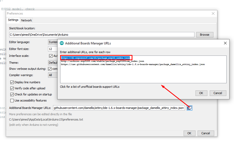
- Deschideți Arduino IDE pe computer, accesați Fișier> Preferințe>
- Lipiți linkul de mai jos în board manager URL (vezi in poza de mai jos)
- https://dl.espressif.com/dl/package_esp32_index.json
Selectarea plăcii:
- Select board > ESP32 ” Wrover Module”
- Flash Mode > QIO
- Flash Frequency > 40MHZ
- Partition Scheme > Huge App (3mb No OTA)
- Upload speed > 115200
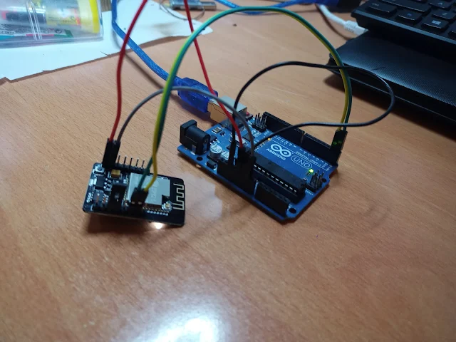
Conexiune ESP32 CAM la Arduino UNO
- Conectați Arduino 5volt la ESP32 CAM 5 volți.
- Arduino GND la GND Placa
- Arduino RX la ESP32 CAM RX și Arduino TX la ESP32 CAM TX
- Pinul de resetare Arduino la GND
- ESP32 CAM GPIO0 la GND
Conexiunile:
Acum placa ESP32 CAM poate fi programata si ar trebui să se observe in Arduino IDE următoarele mesaje:
Sketch-ul de test:
Documentatie proiect:
https://technoreview85.com/how-to-program-esp-32-cam-using-arduino-uno-board/
Pentru întrebari și/sau consultanță tehnică vă stau la dispozitie pe blog sau pe email simedruflorin@automatic-house.ro. O seară/zi plăcută tuturor !


