
Ethernet/IP
- Ethernet is the standard way to connect computers on a network over a wired connection.

- It provides a simple interface for connecting multiple devices, such computers, routers, and switches.
- With a single router and a few Ethernet cables, you can create a LAN (local area network), which allows all connected devices to communicate with each other. It’s base on OSI model (layers model) (see the picture bellow).
- Ethernet was introduced in 1980, and the base standard is still in used today.
- Ethernet data transfer is very high, from 100Mbit/s, to the latest 400Gbits/s.

Ethernet for automotive
Automotive Ethernet is slightly different; because it's a flavor of regular Ethernet, and it’s optimized for vehicul usage. It is a physical layer standard designed for use in automotive connectivity applications. IEEE standardized the technology with 802.3bw (100BASE-T1) expanded to add 802.3bp (1000BASE-T1). In the chart bellow, we compare automotive Ethernet to the more familiar version of Ethernet (100BASE-TX). Main advantages are Bandwidth, High data rate, Flexibility and robustness.

Automotive conditions and requirements
- Environment (EMC, Temperature, etc.) is harsher
- Qualification of Hardware is required
- Validation of Electronic Control Unit (ECU) Hardware and Software is required
- Reliability of the communication channel must be very high
- Start Up Time is shorter
- Latency is smaller
- Repeatability/Predictability is critical
- Safety/ASIL (ISO26262) compliance

Based on the automotive conditions and requirements the Automotive Ethernet must fulfill the following characteristics:
- Reliability
- Predictability
- Flexibility
- Security
A typical example in a normal modern vehicle is represented in the picture bellow, and we can see that high speed comunication is done using Automotive Ethernet, and is distributed through gateways to CAN networks, LIN networks, Flexray and MOST, on lower communication speeds.

Ethernet frame details

Basic and tagged frame
- The IEEE specifications define different formats for Ethernet frames.
The automotive industry typically uses the Ethernet II frame, which can
also contain information for VLAN as an extension. For this reason, a
distinction is made between the basic MAC frame (without VLAN) and the
tagged MAC frame (including VLAN).
MAC addresses
- An Ethernet II frame generally begins with a receiver or destination
address. This specifies which network nodes are to receive a message. In
contrast to the subsequent sender or source address, besides Unicast
addresses, it is also possible to use Multicast or Broadcast addresses.
For an Ethernet frame, there can be only one sender but multiple
receivers.
Ether type- The basic and tagged MAC frames are differentiated with the type field (Ether Type). This generally identifies the contained packet in the payload data area and gives information about utilized protocols in the higher layers (e.g., IPv4). If the Ether Type has a value of 0x8100, the type field is shifted rearward four bytes and a VLAN tag is inserted at its original position.
VLAN tag- A VLAN tag consists of a protocol identifier (TPID) and control information (TCI). While the TPID contains the value of the original type field, the TCI consists of a Priority (PCP), a Drop Eligible or Canonical Form Indicator (DEI or CFI), and an Identifier (VID). Identifier and Priority are mainly used in the automotive industry. The Identifier distinguishes the respective virtual network for the different application areas. The Priority allows optimization of run-times through switches so that important information is forwarded preferentially.
Payload- Following the type
field, the Ethernet II frame contains the payload data area. The payload
has a minimum length of 46 bytes without VLAN tag or 42 bytes with VLAN
tag. It can contain up to a maximum of 1500 bytes in the automotive
industry.
CRC checksum - A CRC checksum is
transmitted at the end of the Ethernet II frame. The value contained in
the checksum is calculated using a standardized algorithm that is
implemented the same way in the sender and receiver. The calculation is
made with all fields of the Ethernet II frame and therefore assures the
integrity of the entire message.
Data incapsulation
This example shows in more detail how OSI PDUs and SDUs are created and encapsulated.
A TCP segment (layer 4 PDU) becomes a layer 3 SDU, which is encapsulated into a layer 3 PDU through the addition of an IP header.
This becomes the payload of an Ethernet frame, which is a layer 2 PDU containing an Ethernet header, layer 2 SDU (the IP datagram) and Ethernet footer.
The receiving device extracts the IP datagram from the Ethernet header and passes it to layer 3; the IP software extracts the TCP segment and passes it up to the TCP software.

ISO/OSI vs AUTOSAR Architecture

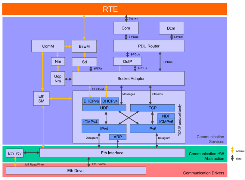
Ethernet from AUTOSAR point of view
Ethernet stack contain the following modules:
- Ethernet Driver - HW driver
- Ethernet Interface - interface between SW and HW driver
- ICMP, IP, UDP, DHCP, ARP - internet suite components
- Socket adaptor, DoIP - automotiv diagnostic over IP
- Ethernet State Manager
- UDP NM module

Ethernet stack in AUTOSAR 4.3
Includes for Eth component

Includes for EthIf (ethernet interface) component

Includes for EthSM (ethernet state manager) component

Includes for EthTrcv (ethernet traceiver) component

Includes for SoAd (socket adaptor) component

Abbreviation / Acronym
ARP Address Resolution Protocol
DEM Diagnostic Event Manager
DET Default Error Tracer
DHCPv4 Dynamic Host Configuration Protocol
DHCPv6 Dynamic Host Configuration Protocol for Internet Protocol Version 6
DoIP Diagnostics over IP
HTTP HyperText Transfer Protocol
IANA Internet Assigned Numbers Authority
ICMPv4 Internet Control Message Protocol
ICMPv6 Internet Control Message Protocol for Internet Protocol Version 6
IETF Internet Engineering Task Force
IP Internet Protocol
IPv4 Internet Protocol version 4
IPv6 Internet Protocol version 6
NDP Neighbor Discovery Protocol
Sd Service Discovery
TCP Transmission Control Protocol
TCP/IP A family of communication protocols used in computer networks
TP Transport Protocol
UDP User Datagram Protocol
UdpNm AUTOSAR UDP Network Management
Documentation
- https://www.autosar.org/Communication services
- https://en.wikipedia.org/wiki/Ethernet
- Autosar Compendium - Part 1: Application & Rte, Oliver Scheid (Author)
AUTOSAR articles (for articles written in Romanian please select your language from right part of webpage)
- https://automatic-house.blogspot.com/search/label/AUTOSAR
- https://automatic-house.blogspot.com/2014/08/calcularea-crc-ului-pentru-standardul.html
- https://automatic-house.blogspot.com/2019/03/autosar1-prezentare-generala.html
- https://automatic-house.blogspot.com/2019/03/autosar2-arhitectura.html
- https://automatic-house.blogspot.com/2019/04/autosar3-comstack-can.html
- https://automatic-house.blogspot.com/2019/05/autosar5-comstack-cantp.html
- https://automatic-house.blogspot.com/2019/07/autosar6-communication-services-in.html
- https://automatic-house.blogspot.com/2021/11/autosar-7-cryptostack-basics.html
- https://automatic-house.blogspot.com/2022/11/autosar-8-communication-over-ethernet.html
- https://automatic-house.blogspot.com/2022/11/autosar-9-error-handling-and-diagnostic.html
- https://automatic-house.blogspot.com/2022/11/autosar-10-memory-stack.html
Thank you for attention !
For questions please contact me on email: simedruflorin@automatic-house.ro.
Have nice day !